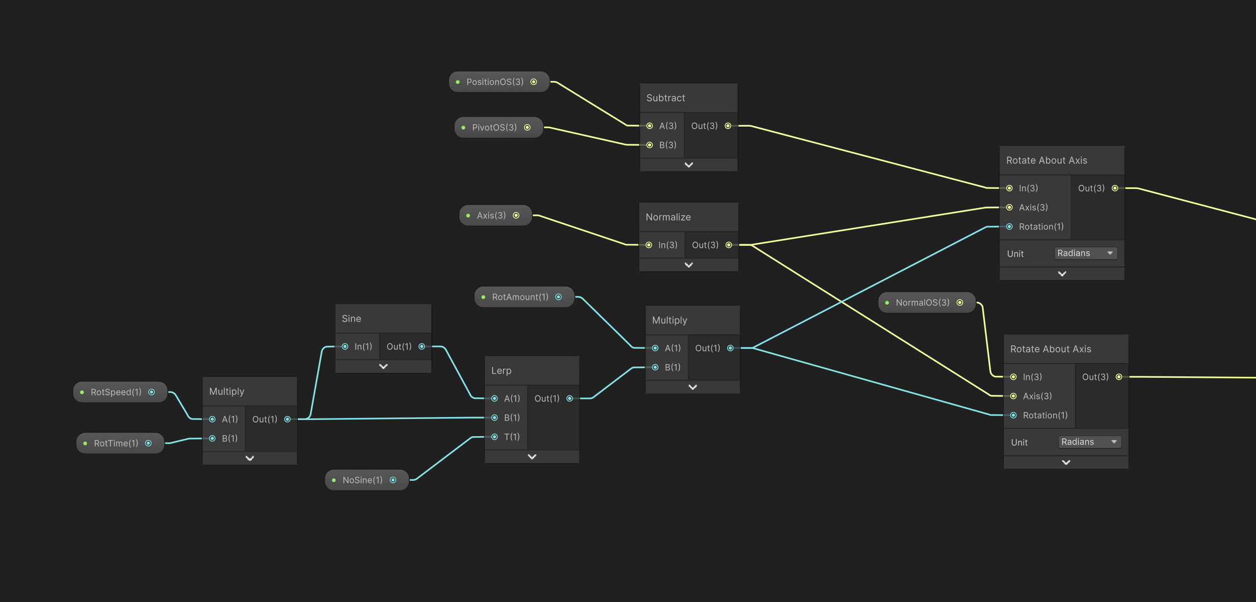
Tech Art • Shader Graph • Unity

Vertex Animation Shader

Overview and introduction

Overview

This project is about a small robot animated through a shader and driven by signals from C#. Vertex colors are used to separate the different parts of the mesh which makes it possible to control and animate them individually. This allows different parts of the robot to move on their own without relying on traditional skeletal animation.

Main components

The final setup is built around a few key systems working together.

  • Vertex Color Masks: Separate the mesh into different areas that can be animated individually.
  • Shader Animation: Drives the animation movement of the shell, wheels, core and antenna.
  • C# Control Signals: Controls how the robot moves, turns, changes between states.
  • Material Property Blocks: Pass C# values into the shader.

Breakdown

A breakdown of the main technical parts used to build the procedural robot animation system.

Vertex Color Masks

Vertex color channels were used to separate the robot mesh into different moving parts. I painted these vertex colors in Maya to define which parts of the mesh should move in different ways. This made it possible to control and animate different areas of the same mesh individually in the shader.

  • Red mask: Outer shell.
  • Green mask: Right inner wheel.
  • Blue mask: Left inner wheel.
  • Yellow mask: Used for the inner core.
  • Alpha mask: A painted gradient on the antenna used to make it bend.

Shader driven motion

Most of the robots animation is handled directly in the shader with different parts of the mesh rotating around their own pivot points.

  • Shell motion: Turning, tilt, and directional motion.
  • Wheel motion: Procedural forward and turning motion.
  • Inner core: Slower forward rotation.
  • Antenna: Bend and spring motion.

Behavior signals from C#

C# handles the robots behavior logic and sends a small set of control values into the shader. These values drive the procedural animation.

  • MoveAmount: How much the robot is moving value 0 to 1.
  • TurnAmount: How much the robot is turning based on -1 to 1 (left and right).
  • Antenna Bend: Controls the antenna motion based on a value 0 to 1.
  • Wheel Angle: Wheel angle calculated in code.

States and visual feedback

The robot uses a few simple states to make its behavior easier to read. These states affect its movement, animation and emissive feedback.

  • Idle state: Jittering animation over time using two sine waves + blue emissive feedback
  • Patroling state Patrolling movement, shel tilt, wheel spinning animation and antenna bend
  • Scaning state: Idle state with shell turning + yellow emissive feedback

Rotation subgraph

This subgraph is used as the base for several of the robots movements. Instead of using bones or animation clips it rotates parts of the mesh directly in the shader.

In my setup the position input is driven by a vertex color mask. This means that the subgraph does not affect the whole mesh at once but only the specific part selected by that mask. This made it possible to animate different parts of the robot separately.

The axis is chosen depending on the type of motion needed. By changing the axis i can decide the direction each part should rotate in.

The movement itself is controlled by values such as time, speed, and rotation amount. These values are combined to create either continuous spinning motion or softer back and forth movement depending on how the subgraph is used.

At the core of the setup is Unitys Rotate About Axis node. This node rotates a position around a chosen pivot point and axis by a given rotation value. In this case it is used to rotate both the vertex position and the normal so the mesh deforms and shades correctly as it moves.

Each of these rotation steps is then combined at the end. The output position from one subgraph can be passed into the next one and then into another. Allowing several motion layers to build on top of each other. This made it possible to create more complex animation by stacking multiple simple rotation setups together.

Rotation subgraph breakdown

Challenges

  • One of the main challenges was getting the wheel motion to feel right. At first i tried to calculate the wheel rotation directly in the shader math and using the angle values but the result felt unstable and looked off. From what I understood part of the issue was that some of the values being sent in were not updated every frame which made the motion inconsistent. To solve this i moved the wheel rotation logic to C# instead. Rather than trying to calculate the full wheel rotation in the shader i calculated it in C# and passed the value into the shader directly. That gave me much more stable and predictable wheel motion.
  • Another challenge was making the animation feel visually appealing especially the small jittering or idle style movement. I wanted the robot to feel mechanical and animated but without making the motion too stiff or static. Finding that balance took some experimentation. What helped was using sine waves layered together with different amplitudes and speeds. That gave the movement a less predictable feel and made the animation feel more alive.

If I had more time

  • If I had more time one of the things I would have liked to add was a chase state. I think it would have been interesting to give the robot a more aggressive animation style in that state with faster movement and maybe quicker blinking to make it feel more intense.